September 24, 2026
The Impact of Roughness Elements on the ABL Profile in CFD
The atmospheric boundary layer (ABL) is the fundamental starting point for CFD simulations in wind engineering. Its main characteristics are the mean velocity profile and turbulence intensity, both strongly influenced by the roughness length () of the terrain.
One of the main challenges when setting up an ABL case is maintaining the target profile throughout the entire region of interest. In this article, we explore how AeroSim addresses this challenge by combining roughness elements with its boundary conditions to generate consistent ABL profiles for different terrain roughnesses.
What does roughness length mean?
The roughness length () represents the aerodynamic effect of the obstacles encountered by the wind as it flows over the terrain.
A smaller roughness length corresponds to a smoother surface, such as the sea or open, flat terrain with very few obstacles. A larger roughness length represents a rougher surface, such as an urban area with buildings and other obstacles.
EN 1991-1-4 (Eurocode 1) defines five terrain categories, each associated with a characteristic roughness length:
| Terrain category | Description | (m) |
|---|---|---|
| 0 | Sea or coastal area exposed to the open sea | 0.003 |
| I | Lakes or flat and horizontal area with negligible vegetation and without obstacles | 0.01 |
| II | Area with low vegetation such as grass and isolated obstacles (trees, buildings) with separations of at least 20 obstacle heights | 0.05 |
| III | Area with regular cover of vegetation or buildings, or with isolated obstacles with separations of maximum 20 obstacle heights (such as villages, suburban terrain, permanent forest) | 0.3 |
| IV | Area in which at least 15% of the surface is covered with buildings and their average height exceeds 15 m | 1.0 |
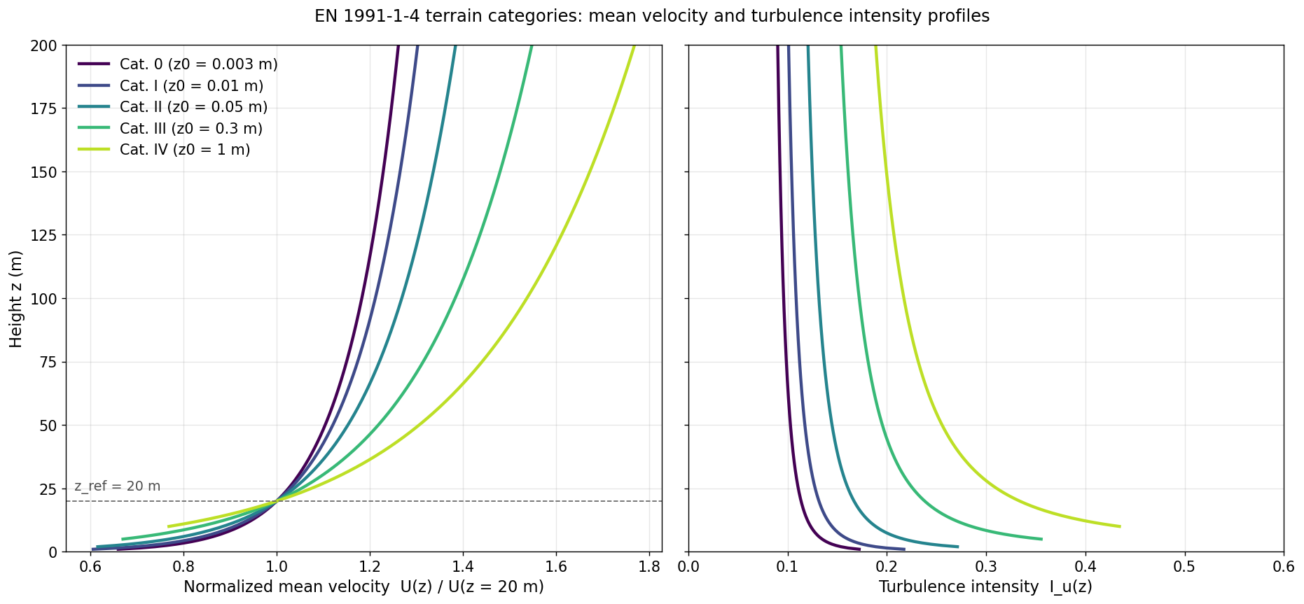
The roughness length has a significant effect on both the velocity profile and the turbulence intensity.
As the roughness length increases, the terrain generates more turbulence and the velocity decreases more gradually as it approaches the ground. The result is a lower near-ground velocity and a higher turbulence intensity.
The effect can be seen in the plot below, which compares the five terrain categories defined by the Eurocode.
How do we represent roughness length in CFD?
The next step is to reproduce these terrain effects in the simulation.
In physical wind tunnels, this is typically done using a combination of roughness elements, such as cubes or other obstacles, distributed along the floor of the tunnel. In CFD, we have more freedom to explore different approaches because we are not constrained by the physical limitations of a wind tunnel.
At AeroSim, we start by using an ABL wall model at the ground to reproduce the desired .
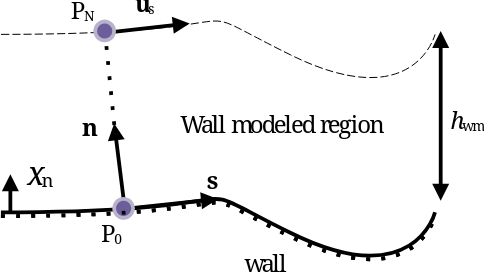
However, this alone is not enough to maintain the target profile. As the flow develops downstream, it gradually redevelops toward a smoother terrain condition. Without physical elements generating the turbulence required to sustain the prescribed roughness, the velocity and turbulence profiles progressively depart from the target ABL.
To compensate for this, we introduce roughness elements into the domain, following a concept similar to what is commonly done in wind tunnels.
This introduces additional considerations, however. Unlike a physical wind tunnel, the CFD solution is also affected by factors such as mesh resolution and the turbulence model. The geometry, spacing, and size of the roughness elements therefore need to be calibrated for the conditions of the simulation.
This means that some testing is required to determine which configuration best reproduces the desired ABL profile.
Choosing the roughness elements
At AeroSim, we have tested a variety of roughness elements. Our current approach uses plates whose height is scaled according to the target .
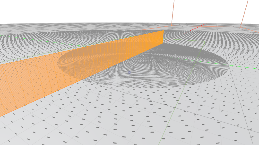
The plates are 6 m wide, with heights of 1 m for category I, 2 m for category II, 5 m for category III, and 8 m for category IV.
There is no universally correct choice of roughness element. Different geometries can produce similar effects, and their performance depends on the specific combination of terrain, mesh resolution, turbulence model, and domain configuration. Ultimately, the only way to determine whether a given configuration works is to test it under the conditions of the problem.
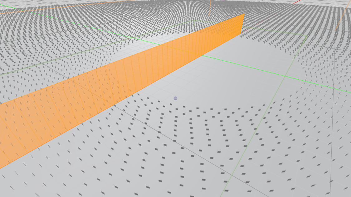
For most applications, this approach is sufficient. This is particularly true for high-rise buildings, where the flow close to the ground is generally less critical than it is for low-rise structures.
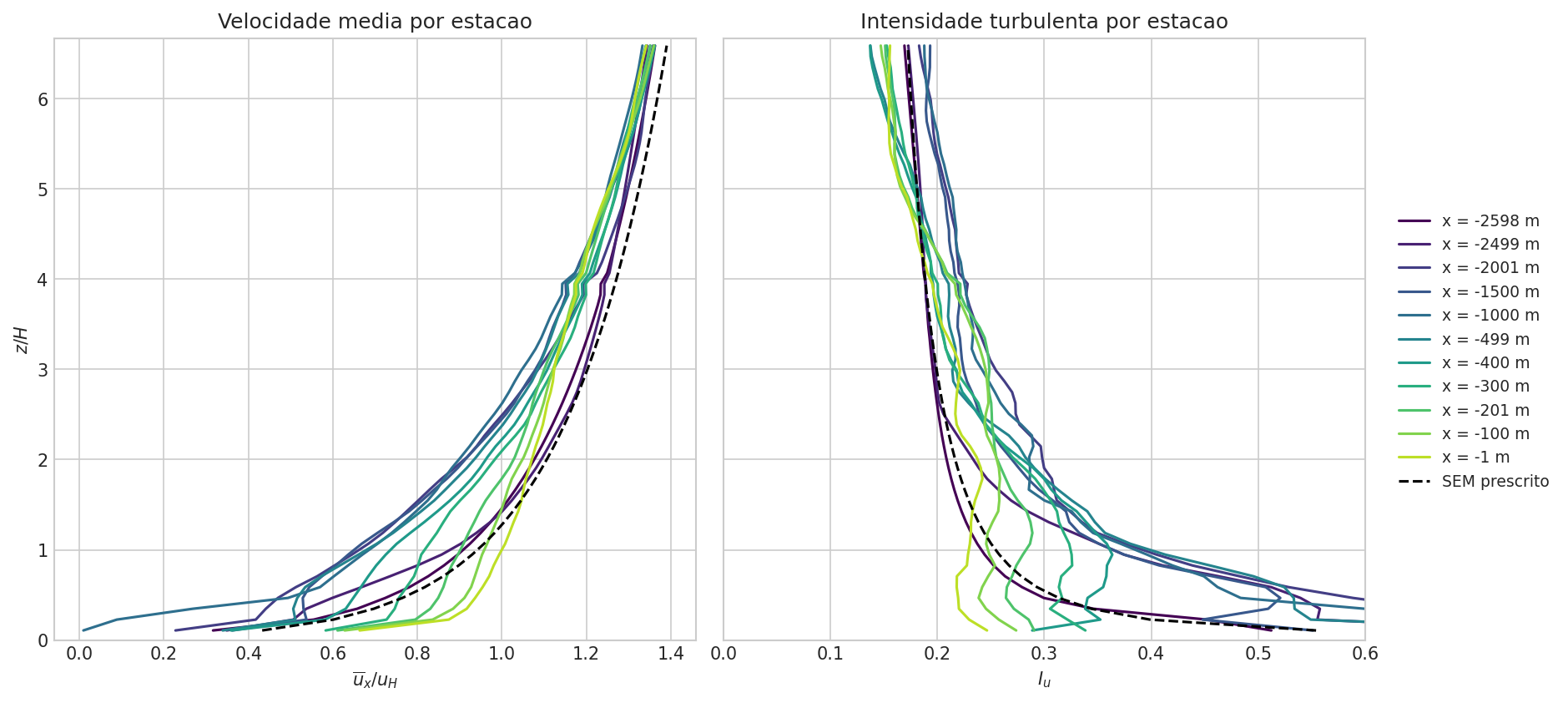
However, problems arise when the region of interest becomes large enough for the flow to redevelop before reaching the site. In these cases, the lower part of the flow can progressively return toward a smoother terrain condition, effectively moving toward category 0.
An example is shown below. The roughness elements end at . Downstream of this point, the near-ground velocity begins to accelerate while the turbulence intensity decreases, indicating that the flow is progressively redeveloping toward a smoother surface.
Maintaining the profile through the region of interest
To address this issue, we have started adding fins within the region of interest.
The goal of these fins is not to represent physical obstacles. Instead, they are designed to generate the velocity fluctuations and turbulence needed to maintain the desired ABL profile, while minimizing the formation of large-scale vortices and other aerodynamic structures that could interfere with the flow around the building.
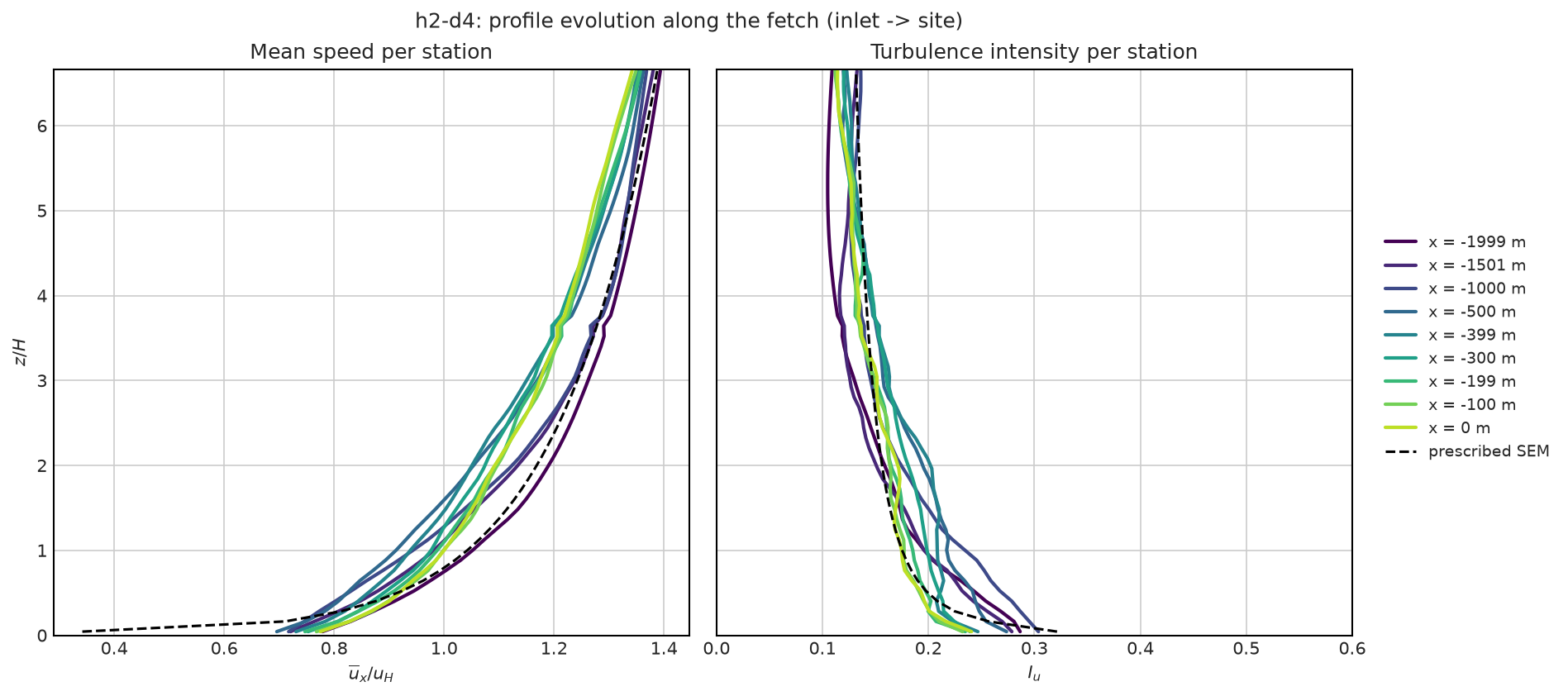
With these additional elements, the flow maintains a much more consistent profile throughout the domain.
Both the mean velocity and turbulence intensity remain close to the prescribed SEM profile all the way to the site, reducing the redevelopment observed when the region of interest is left empty.
Conclusion
The roughness length () is a fundamental parameter when defining an atmospheric boundary layer for CFD simulations. It affects both the mean velocity profile and the turbulence intensity, and reproducing these characteristics consistently throughout the domain is essential for reliable wind engineering simulations.
At AeroSim, we combine an ABL wall model with carefully designed roughness elements to generate and maintain the desired terrain conditions. For larger regions of interest, additional fins can be used to prevent the flow from redeveloping toward a smoother terrain condition before reaching the site.
The final configuration is therefore not simply a matter of prescribing a at the ground. The geometry and distribution of the roughness elements, together with the mesh and turbulence model, all play a role in determining the effective ABL that develops in the simulation.
If you want to learn more about AeroSim and explore its capabilities for yourself, email us at [email protected] and get in touch.

Waine Oliveira Jr.
CEO & Founder
Waine is a computer engineer, with over 7 years of hands-on experience in numerical simulations for Computational Fluid Dynamics (CFD) using the Lattice Boltzmann Method (LBM).