
Wind tunnel tests are designed to measure aerodynamic forces in an object, and then convert these results to quantities that can express such forces in the full-scale object. The conversion of loads from prototypical to full-scale is achieved with aerodynamic coefficients. In guidelines for wind loading of structures, three types of aerodynamic coefficients are commonly used: pressure coefficient (Cp), shape coefficient (Cf), and force coefficients (CF or CM). In this article, we delve deeper into how these coefficients are measured and defined within wind tunnel tests.
Wind tunnel measurements with pressure taps
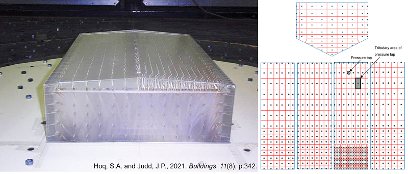
In order to capture the pressure distribution over the object's surface, pressure taps or sensors are strategically placed at various locations. These taps are connected to pressure transducers, which convert the pressure readings into electrical signals. There could be hundreds of pressure taps simultaneously acquiring the signals that will then be converted into forces. To each pressure tap, a tributary area is associated, so that the pressure measured at tap i can be transformed to normal force at area i. The tributary area determines how a load is shared among neighboring components based on their relative sizes and positions. The figure below shows an example of pressure taps and tributary area.
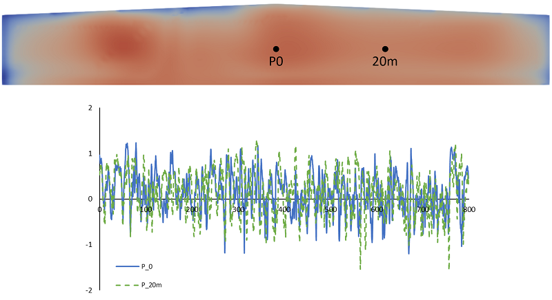
Each tap acquisition looks like the pressure signal below. Atmospheric wind turbulence causes the pressure to oscillate with a wide spectrum of frequencies. Also in the figure, we can see that the pressure signal of tap located 20 meters (real scale) from the original probe does not coincide with the first tap. The non-concomitance of wind gusts means that the resulting force in a larger area of influence, from the original tap to the 20 m distant, is less than each individual tributary force.
Pressure coefficient (Cp)
The pressure coefficient is a normalization of the pressure measured at a certain location (1-dimensional). It is defined by the formula below:

where ρ is the air density, Vref is the reference velocity and p∞ is the static pressure (measured separately in the wind tunnel's freestream region). The pressure coefficient can be internal, when measured inside the object, or external, when measured on the outside.
By systematically measuring Cp at various locations on the object's surface, researchers can create pressure distribution maps, which provide insights into regions of high and low pressure and contribute to the overall understanding of the aerodynamic forces involved.
Since pressure coefficients are associated with individual locations, their area of influence is limited to the tributary area (small). They are recommended for the design of small elements, such as components and cladding.
Shape coefficient (Cf)
As seen before, large areas of influence encompassed by many taps, have resulting forces that are lower than the individual tributary forces. The shape coefficient is a measure of the resulting pressure force within an area of influence AI (2-dimensional). It is defined by the formula below:

where At are the tributary areas. The larger the area of influence, the more uncorrelated the signals Cp,t are, reducing the resulting Cf.
With the shape coefficient, designers can evaluate normal forces over large areas, such as facades or roofs of buildings. While some wind codes do refer to these coefficients as shape coefficients, others define pressure coefficients for large areas (for instance, “Cpe,1” and “Cpe,10” in the EU 1991 1 4). Nonetheless, they all represent the same load effect.
Both pressure and shape coefficients represent the normal force exerted by pressure. Different statistical properties can be derived from them, such as mean, root-mean-square, maximum and minimum coefficients. Also, when a surface is subject to external and internal pressures, a net pressure coefficient can be derived. In a subsequent article, we will explain how the statistical properties of the aerodynamic coefficients are used to obtain the design loads.
Force Coefficient (CF or CM)
A building has many surfaces exposed to wind actions. For the main structural resisting system, it is necessary to determine the global forces and moments acting over the building as a whole. The force coefficient is a normalization of a resultant force acting over a body (3-dimensional). The force coefficient for the X direction is defined by the formula below:

where Aref is a reference area, commonly defined as the projection area of the body in the wind direction. Similarly, the moment coefficient in the Z direction is defined as:

Force coefficients can also be calculated for building elements, such as columns, beams, canopy roofs, etc. When an element or building exposed to wind has a large area parallel to the direction of incidence, the friction force caused by viscous drag can become an important portion of the overall resultant force. Friction force coefficients are given in wind codes either discriminated for some surface configurations or accounted for in the force coefficients of some usual building typologies.
Conclusions
In the realm of building aerodynamics, understanding pressure, shape, and force coefficients is essential for designing structures to withstand air forces effectively. The key takeaway from the above discussion is as follows:
Pressure coefficient (Cp) → defined for a point (1-D)
Shape coefficient (Cf) → defined for a surface (2-D)
Force coefficient (Cp) → defined for a volume (3-D)
Wind tunnel tests enable the evaluation of these actions on a prototypical scale and the subsequent transfer of results to full-scale. As we refine our grasp of these coefficients, we open doors to innovative designs that harness aerodynamics effectively. In this ever-evolving field, mastering these coefficients leads to the design of safer and more efficient structures.