
Buildings situated atop hills or slopes experience amplified wind velocities due to the Venturi Effect, resulting in significantly higher loads compared to those on flat terrain. Therefore, the topography speed-up factor, a parameter that indicates the proportion of velocity increase due to the shape of the terrain, is considered in all major wind codes. Wind codes provide analytical solutions to estimate the topography speed-up factor for simplified terrain. However, real terrains have complex topographic sections, leading to significant uncertainties in the structural project.
This post presents a comparison of computational fluid dynamics (CFD) performed by AeroSim and experimental results of the topography speed-up factor in a variety of geometries. The developed methodology uses a digital model of the surrounding terrain combined with the earthwork project. In this post we demonstrate that a carefully implemented CFD solution is a viable and more accurate alternative to analytical solutions for the topography speed-up factor. An extended version of this work can be found in the proceedings of the XIV Brazilian Congress of Bridges and Structures.
What is the Topography Speed-Up?
To incorporate topographic effects on wind velocity, the major wind codes define a correction factor for the basic wind speed. This factor, along with others such as roughness and reliability factors, compose the design wind speed. The most common definition for the topography speed-up factor (S1) is shown below:

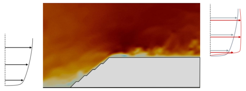
The increase in wind velocity is explained with the figure below. The velocity profile at the windward side of the slope is the typical atmospheric boundary layer profile. Across the slope, the wind suddenly has a constricted section to go through, and the mass conservation law requires that it accelerates. The air flow separates at the crest, making a recirculation region below which the mean velocities are small but turbulence is high. The velocity profile at a section just past the crest is shown in the right hand side of the illustration. Notice that the local mean velocities can be much higher than in the typical atmospheric boundary layer.
When the terrain speed-up factor is not taken into account, the wind loads are significantly underestimated. This can cause a number of incidents such as roofing tear offs, and overturning walls.
Comparison Results
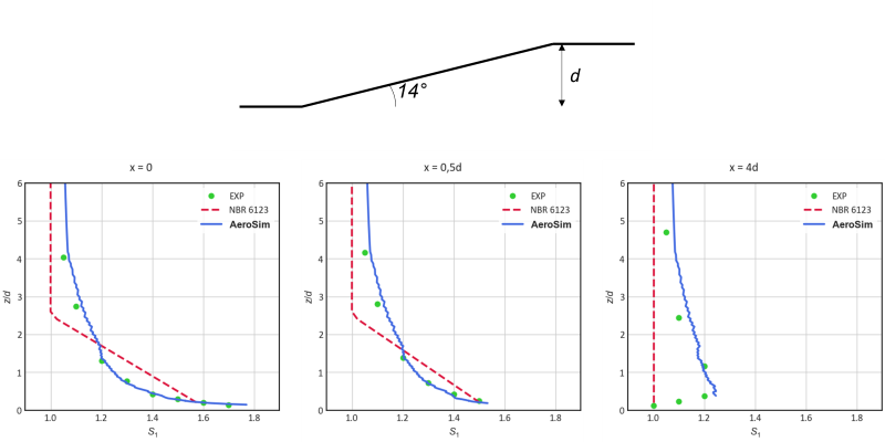
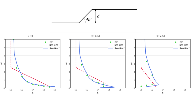
AeroSim has developed a high performance CFD solver based on the lattice Boltzmann method. The turbulence treatment is given by the large eddy simulation method. To validate the numerical methodology, experimental results obtained from a wind tunnel were used and presented in two published works in the literature. The initial comparison is based on the work by Bowen and Lindley (Boundary-Layer Meteorology 256-271, 1977), and the results are presented below. The red line is the analytical solution from the Brazilian wind code NBR 6123. It can be noted that, for relatively low z, the analytical solution overestimates the topography speed-up factor at the crest of the slopes. The simulated results closely match the experimental ones. The high S1 factors obtained at the crest undergo significant reductions along the leeward path, reaching values of around 1.4. The analytical solution maintains a tendency to overestimate the value of S1 near the ground, indicating values of approximately 1.6. For long distances away from the crest, the wind code error trend is reversed, i.e., it underestimates the real wind velocity, leading to structural risks. Bowen and Lindley (1977) measured topography speed-up factors higher than 1.1 that persisted at distances greater than 10 times the slope height. The numerical results again closely match the experimental results in regions far from the crest.
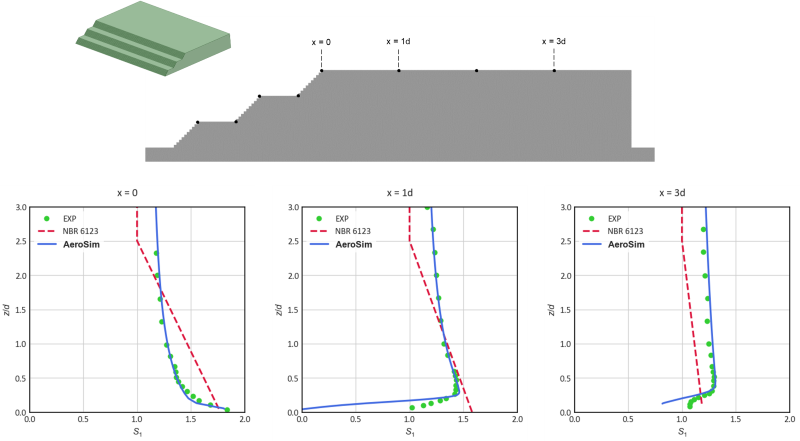
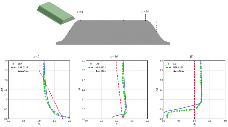
For more complex topographic sections, the obstacles below have also been tested, based on Scotton (Doctorate thesis, UFRGS, 2020). It is evident that the CFD process that was employed reproduces the experiments with good accuracy, even for more realistic geometries. It is particularly interesting the location “S” at the leeward side of the hill, for which a topographic factor of wind protection could be used.
AeroSim’s Process for Terrain Effects
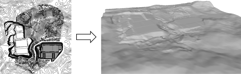
Building a digital elevation model (DEM) involves a multi-step process that utilizes data from earthwork projects and surrounding topography obtained through satellite data. The first step is to integrate the altimetry information from various sources, such as GNSS receivers and remote sensing by drones and small aircraft, along with precise satellite data. This data is then combined to create a high-resolution representation of the terrain's elevation and topographic features. The resulting DEM serves as a detailed three-dimensional map of the region. Subsequently, the DEM is employed in wind tunnel analysis to study the topographic effects on wind speed distribution. By simulating wind flow over the terrain using computational fluid dynamics (CFD) and the wind tunnel's controlled conditions, the topographic factor can be calculated, indicating the extent to which wind velocity is influenced by local accelerations and blockages due to the terrain's shape. This process enables a comprehensive understanding of wind behavior around structures situated on hills, slopes, or other complex terrains, thus aiding in the design and assessment of their safety and performance.
Conclusions
The results highlight the substantial advantages of using AeroSim’s CFD processes to determine topographic effects on wind profiles. While analytical solutions offer practicality, they exhibit severe limitations when compared to real-world phenomena. Analytical approaches tend to provide excessively conservative values near slope crests while underestimating the speed-up factor over longer distances. In contrast, our numerical solutions consistently demonstrated high accuracy when compared to experimental measurements.
AeroSim's solutions for wind flow over complex topography offer significant advantages for structural projects. By reducing uncertainties in wind load estimation, our simulation processes offer enhanced safety, quality, and cost-effectiveness, especially for structures with facades located near hill crests and slopes.