The easiest way to place building parts in a CFD domain
The long journey to transfer AEC models into a computer simulation.
 The easiest way to place building parts in a CFD domain
Simulating wind flow around buildings in CFD is a challenging task due to the difficulty of accurately incorporating solid parts into the fluid domain. Complex building geometries require precise representation at the fluid-solid interface, often demanding labor-intensive body-fitted meshes. This complexity is amplified in scenarios with irregular shapes, multiple structures, and unsteady wind conditions, making it difficult to resolve critical flow features like boundary layers and vortex shedding. However, alternative methods offer great flexibility, simplifying the meshing process and making it easier to handle complex or irregular geometries effectively.
Including solid models into CFD softwares
Anyone familiar with Computational Fluid Dynamics (CFD) has likely faced the challenge of simulating flow around complex geometries. The process requires striking a delicate balance between preserving the physical accuracy of an object’s characteristics and simplifying the geometry to improve mesh quality for numerical stability.
The traditional approach to include a solid body, like a building, in CFD simulations involves creating a mesh that conforms to its shape. Ideally, this mesh should resemble a structured grid that smoothly adapts to the geometry, much like a flexible material stretched over a surface. Achieving this can only be made by manually tailoring the mesh, and it is close to impossible if the body includes lots of small features, close gaps or angular corners. Automated mesh generators can alleviate the situation by building unstructured grids with inhomogeneous cells, offering greater flexibility and requiring less manual intervention. However, these grids can suffer from poor cell quality, such as non-orthogonality and skewness, which may lead to computational instability, longer simulation times, and sometimes invalid results. Moreover, mesh construction is resource-intensive, often involving an iterative process of trial-and-error that can take multiple minutes or even hours on each attempt.
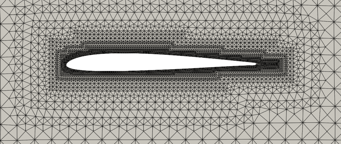
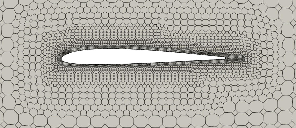
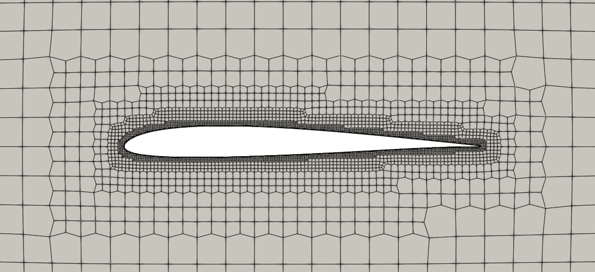
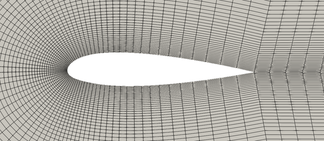
Different mesh topologies around an airfoil
For these and other reasons, geometry simplification and mesh construction is a central topic for the CFD community, with new algorithms and software developed each year to address these issues.
From drawings to 3D models in AEC
But what about the geometries we use in architecture? Architects and engineers are used to creating and dealing with multiple models of buildings on a daily basis, so digital representations are not scarce. Unfortunately, though, those models are rarely (if ever) built considering its usage in CFD softwares.
Structural models, for example, are used to analyze the load resistance and stability of the building. Therefore they will usually contain only structural elements, such as columns, beams, load-bearing walls, slabs, braces, etc. So, in order to use these models to measure wind loads or analyze how a building impacts the air flow of its neighborhood, it would be necessary to first reintroduce the elements of the exterior façade.
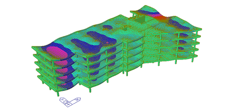
Structural model without façade walls
Architectural models, on the other hand, are used to visualize the design, layout, and aesthetics of a building. Those are high-detail models for client presentations containing walls, windows, doors, finishes, spatial layouts, and sometimes even furniture and other objects. Building Information Model (BIM) goes further and integrates all disciplines (architecture, structure, MEP) into one model for better coordination and project management, which can even contain non-geometric data like materials, quantities, costs, and schedules (4D and 5D BIM). These models often require simplification to retain only the exterior features relevant to wind resistance. This simplification can be even more time-consuming than adding elements to the structural model, especially when dealing with highly detailed or complex designs.
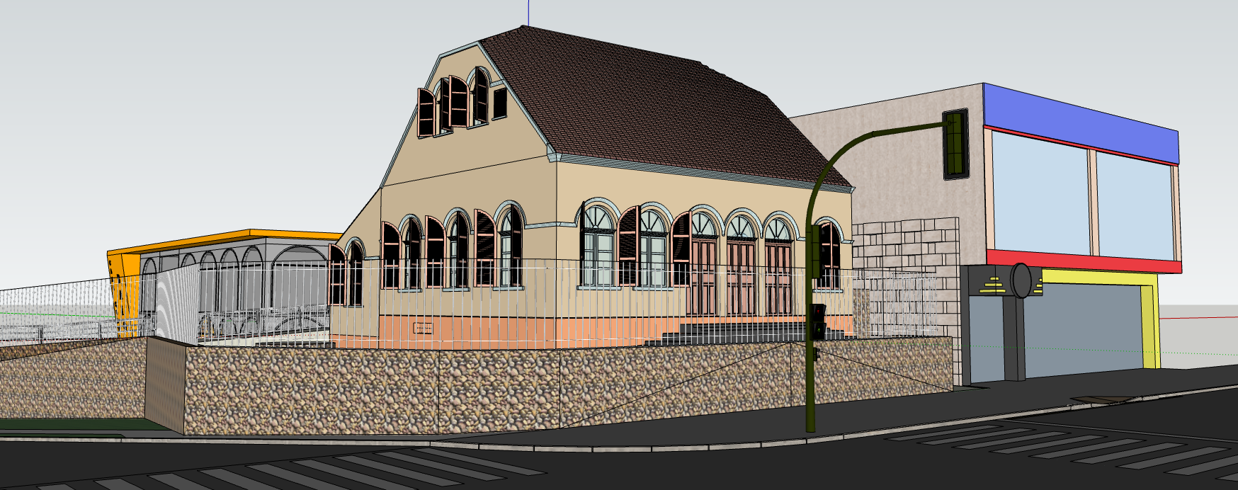
Architecture model full of details
Therefore CFD softwares used for construction must be robust and flexible enough to handle complex and incomplete geometries.
Working with surfaces instead of volumes
Although the construction of a conformal grid around the body is the most common way to represent a solid in a CFD simulation, it is not the only one. Alternatives, like level-set methods, smoothed-particle hydrodynamics and immersed boundary method (IBM) have been used for decades, each offering distinct advantages and drawbacks.
In the CFD software developed by AeroSim we choose to use the IBM method to represent buildings and the topography of a project. Why?
In this approach, the solid body is embedded within a fixed cartesian or structured grid and the no-slip boundary is enforced by a thin force field. This method allows for easy mesh construction, regardless of geometry complexity, as the primary concern is determining the appropriate refinement level for different regions of the domain.
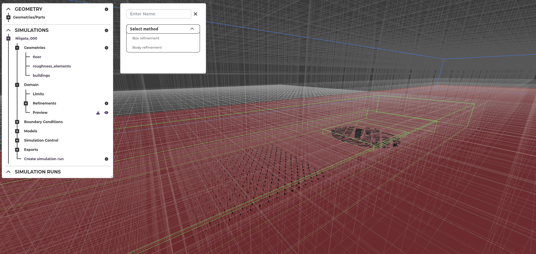
Mesh with boxes defining refinement regions
But if that is the case, why isn’t IBM the default method used in most CFD softwares, instead of body conformal mesh construction? A similar level of accuracy can be achieved by both methods, but IBM usually requires a higher number of mesh elements, especially when the walls are misaligned with the background mesh. Since the Finite Volume Method has to calculate the interactions between all the neighbouring cells, the increase in this number has severe implications to the performance.
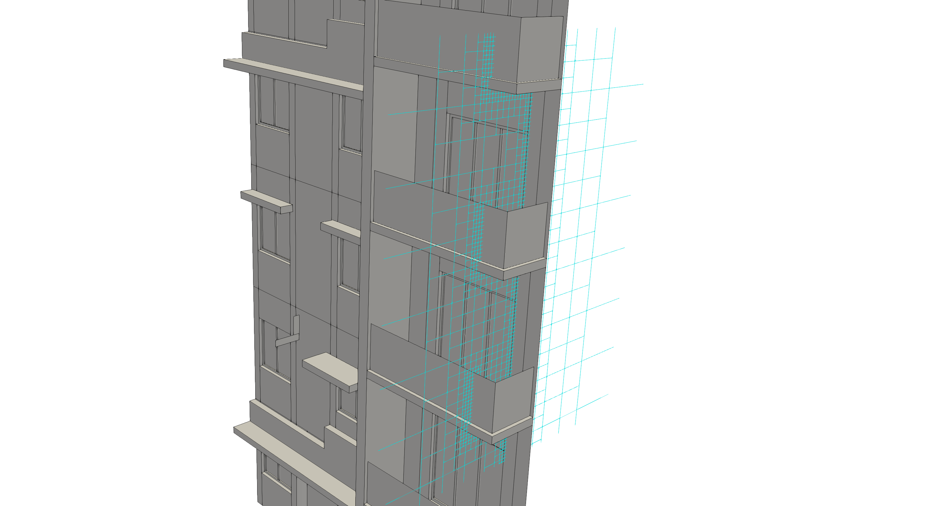
Detail of the final mesh obtained
At AeroSim, we’ve addressed this challenge by leveraging heuristics to optimize the simpler mesh structure and employing the parallelization capabilities of the Lattice-Boltzmann Method. This approach allows us to manage a larger number of mesh elements without sacrificing simulation speed, making IBM a highly efficient method for simulating complex geometries like buildings.
Summary
In this article we have seen that simulating wind flow around buildings in CFD is challenging due to the complexity of incorporating solid geometries into fluid domains. Additionally, construction industry models, like structural and architectural designs, often require simplification before being suitable for CFD analysis. It was shown how traditional methods, such as body-fitted meshes, require precise mesh construction that adapts to the geometry which can be time-consuming and computationally intensive. Alternative methods, such as the Immersed Boundary Method (IBM) offers flexibility by embedding the solid body into a fixed grid, simplifying mesh generation regardless of geometry complexity.
AeroSim addresses the challenges of computational wind engineering by combining high-performance computing with the Lattice-Boltzmann Method in its CFD software, delivering high-accuracy simulations capable of handling complex building geometries efficiently, making it an ideal solution for the construction industry.

Aron Zavelinski
Aron is a computational wind engineering (CWE) researcher specializing in wind effects on safety and comfort.