How to create a computational mesh in LBM?
See why it is so easy to create a mesh for LBM simulations
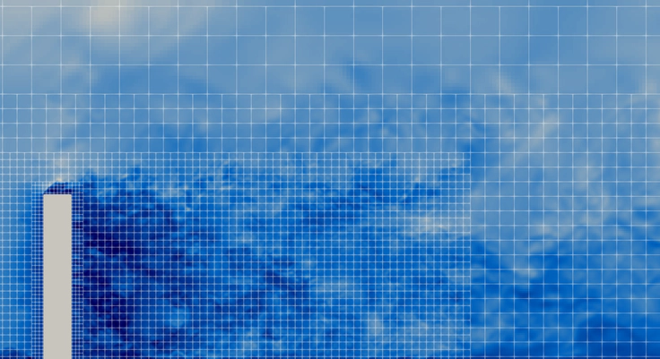 Multi block mesh in LBM
When migrating from a finite volume method to the lattice Boltzmann method, many questions about meshing and geometry simplification may arise. Various strategies and quality criteria from finite volume methods may not be applicable to LBM. However, there are best practices for LBM meshes, as well as particularities that are very important to understand. This article explains how multiblock meshes work in LBM, and provides our main tips for good simulation performance.
The LBM mesh is a point cloud
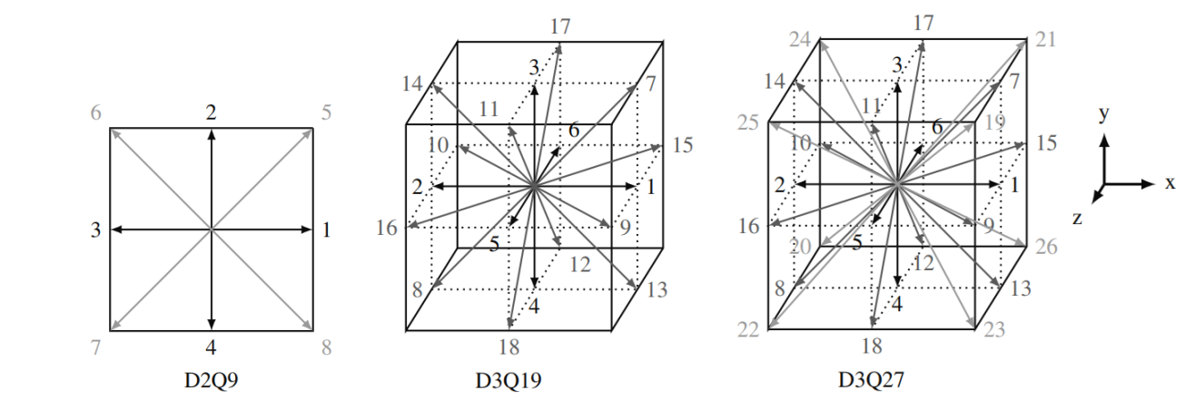
You may have seen in our previous article that LBM solves the Boltzmann equation in phase space. When this equation is discretized, it becomes the lattice Boltzmann equation, as the space is subdivided into a finite number of lattices. These structures are defined by a center and several velocity vectors. As shown below, different lattices arrangements can be created, and the more velocity directions there are, the higher the accuracy and numerical stability of the simulation. The simulation domain must be filled with these structures. Since lattices have fixed dimensions, the LBM mesh takes the form of an isotropic point cloud.
When working with large domains and high Reynolds numbers, it is impossible to use a single refinement level, as the node (lattice) count would be astronomical. This is why multiblock meshes are so necessary. With them, refinement zones can be defined, always with a 1:2 ratio. Thus, the zoning refinement, that is so important for CFD simulations, is also applicable to LBM.
How about the walls?
The natural way to represent walls in LBM is by using the nodes themselves as boundary conditions. Simply define a set of nodes where the no-slip condition is to be applied and assign an appropriate boundary condition to them. For example, the bounce-back condition reflects the populations back to where they came from, generating the no-slip effect while simultaneously conserving mass and momentum of the populations.
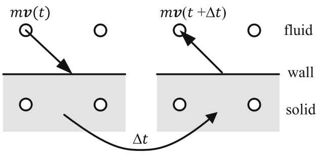
Krüger et al, The lattice Boltzmann method: Principles and Practice.
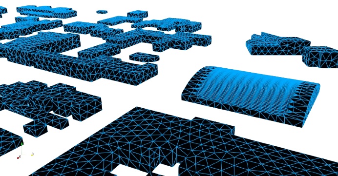
As you can imagine, the bounce-back condition is not ideal for working with complex geometries or with moving/deformable objects. This is why the Immersed Boundary Method (IBM) emerges as a very interesting alternative. IBM represents the solid body as another point cloud, which is then superimposed onto the fluid mesh. The no-slip condition, or any other velocity condition you wish to impose, including wall models, are applied to the fluid through a force field.
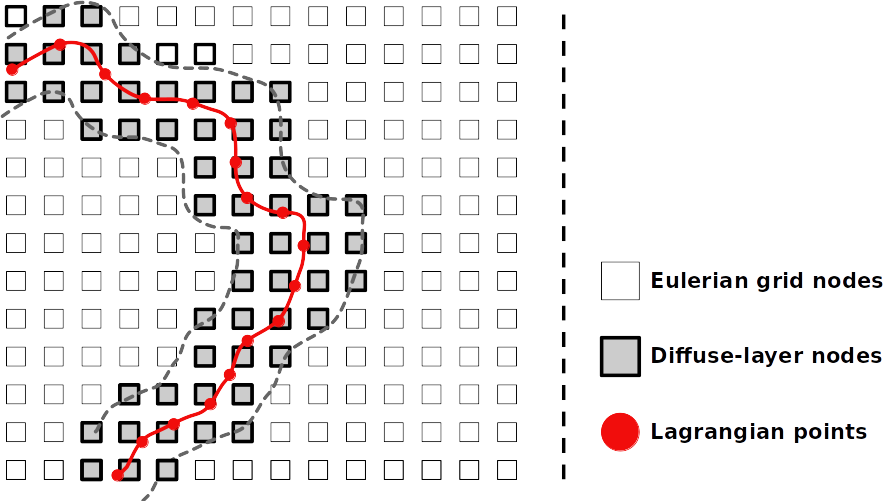
Mesh generation with IBM is very simple in the AeroSim software. Using STL files to represent the bodies, the program creates the solid mesh using the triangle centers. Additionally, the program automatically refines the STL triangles so that the element size (Δx) matches the magnitude of the fluid mesh in which it is immersed.
Mesh robustness with LBM
One of the main complaints from computational fluid dynamics (CFD) users is that the process of geometry simplification and mesh generation in traditional solvers is a time-consuming trial-and-error process. In this aspect, IB-LBM offers a huge advantage, as the fluid and solid meshes are overlapped. Therefore, small imperfections in the geometry, such as intersecting faces or openings, do not hinder the mesh generation process. There is no need to ensure watertight parts. The quality of the geometry can impact the quality of the simulation, of course, but it does not obstruct the mesh generation process due to small imperfections.
Example of mesh generation
The example below shows a mesh generated for calculating wind pressures on a 255-meter-high building. This building is surrounded by other low or medium-height buildings, extending 320 meters in radius. The dimensions of the digital wind tunnel were defined as 6000x800x1000 meters, with a base scale of Δx = 12 m. The strategy for creating a mesh for atmospheric boundary layer flow requires defining a corridor for the development of the velocity and turbulence profile. For this purpose, a level 2 corridor (with Δx = 3 m) was defined, extending 2300 meters. Two transition levels were also defined to properly capture the turbulent wakes generated by the building. Finally, a body refinement with level 5 (Δx = 0.375 m) was applied to the building itself. The total node count was over 42 million elements in this example. The processing time to generate this mesh? 20 seconds.
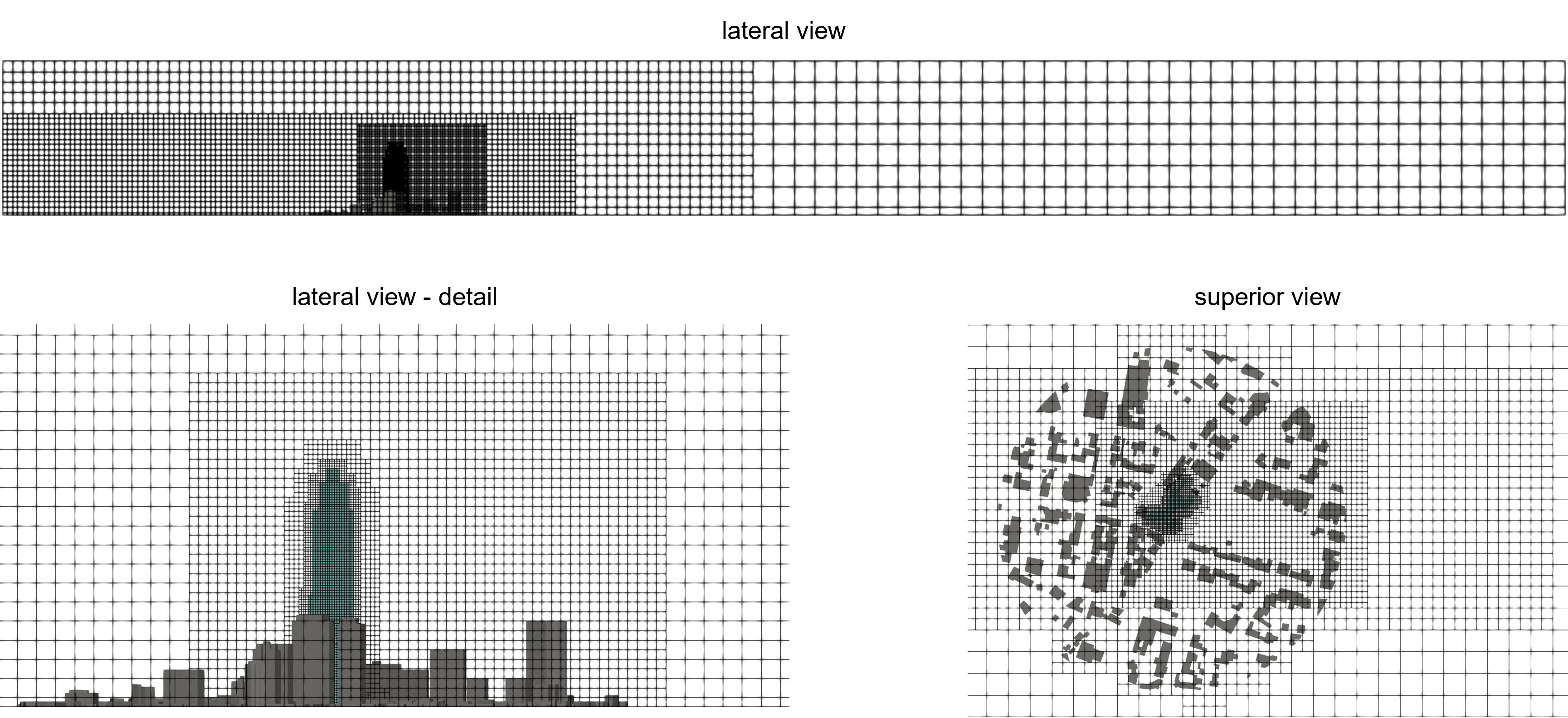
The AeroSim software informs you how long your case will take to process, based on your mesh and the configured sampling time. In this case, the preview indicates a clock time of 15 hours for a sampling time of 20 minutes, running on a GPU NVIDIA RTX 5500.
Summary
Mesh generation in LBM is a very simple process once you understand that the fluid volume must be filled with a cloud of points. The multiblock mesh works the same way that all users are familiar with: creating refinement zones as needed to resolve walls or turbulence. The most relevant point for new users is the mesh robustness, eliminating the need for watertight geometries and reducing the iterative process of geometry and mesh from hours to minutes.
In the next article, we are going to show real wind engineering problems that have been successfully solved with LBM simulations, taking advantage of its exceptionally fast meshing process.

Alan Lugarini
Alan is a computational fluid dynamics (CFD) scientist specializing in turbulence simulation techniques for wind actions.
